Once again it’s one of the posts, which are rather not my standard, but I couldn’t find any info about repairing this bluetooth speaker, so I thought I’ll share how I got it to work: What I’ve done was to:
- replace a battery with a replacement,
- replace a slide switch, since my speaker was randomly turning on and off,
- replace a Micro-USB port to a USB-C,
- put some replacement on a hinge on the slide switch, since the gum was damaged.
First of all, let me show you what was needed:
- Alps-Alpine SSSS711403 slide switch (you must also keep the old one temporarily, you will find out why later in the post)
- AHB723938 4.4 Wh battery (Amazon.com, gustaf.pl, AliExpress (they don’t ship it to EU))
- USB-C port with 5 pin layout
- Little help from my friend who modeled and printed me a hinge
Disassembly
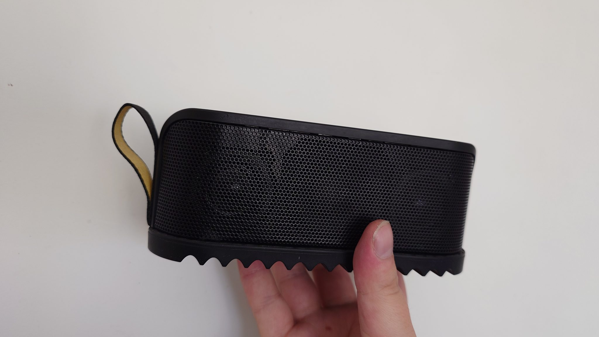
You have to take off the gum underneath holding a Jack cable, then you have to use Torx 6 screwdriver to unscrew two ones holding the part with a black/yellow hook. Then, you slide it off.
Next, you have to take off the upper part of the plastic with a metal spudger (I broke a plastic one). During that, you must use 99% IPA, since the part is glued from inside. 99% IPA is safe, so you can pour it a little bit into a place where you pry the plastic. Be sensitive, it’s easy to break it. I started pulling it a bit from control panel, then a bit from a hook side and then I got it off.
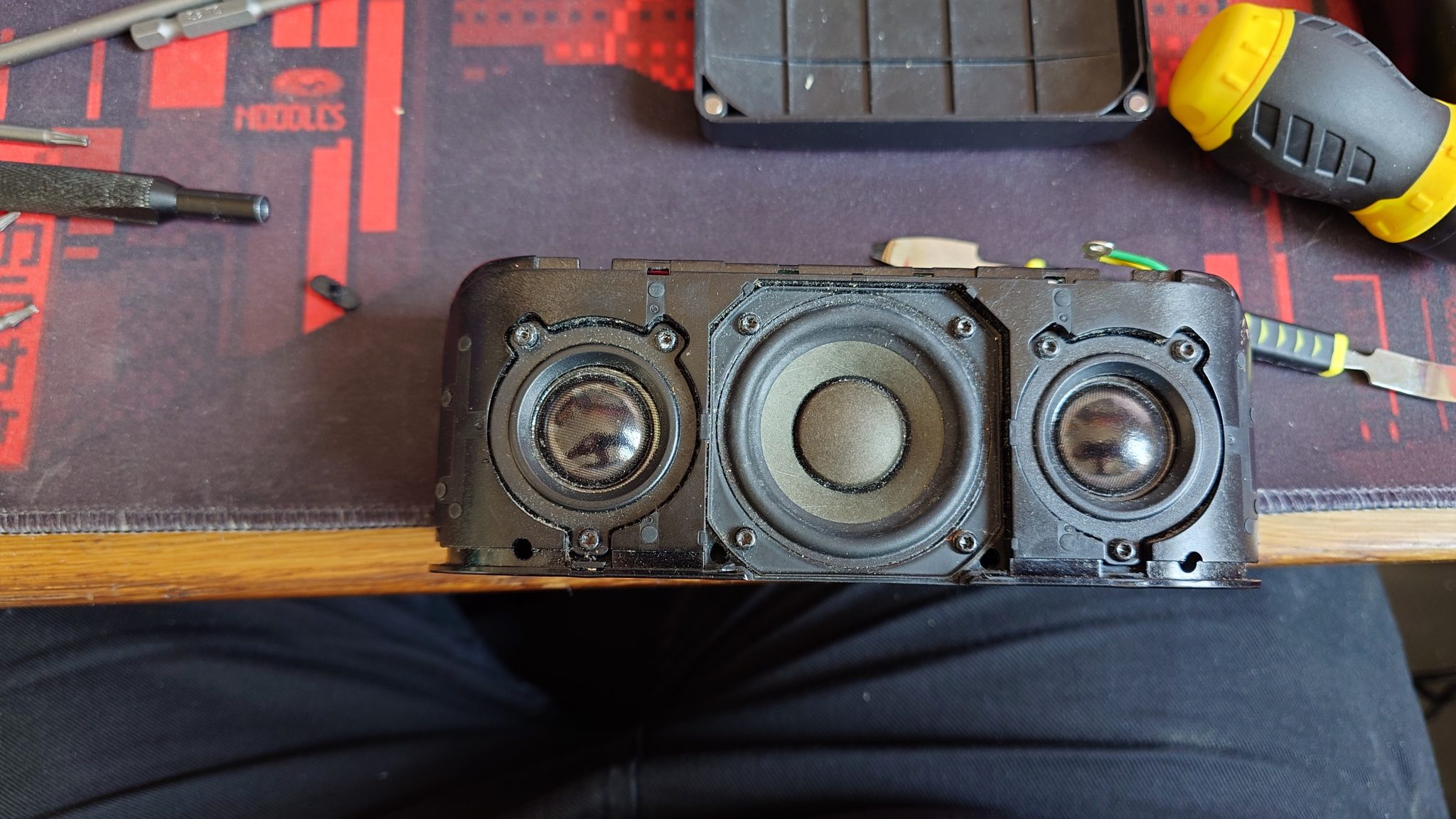
That’s the result:
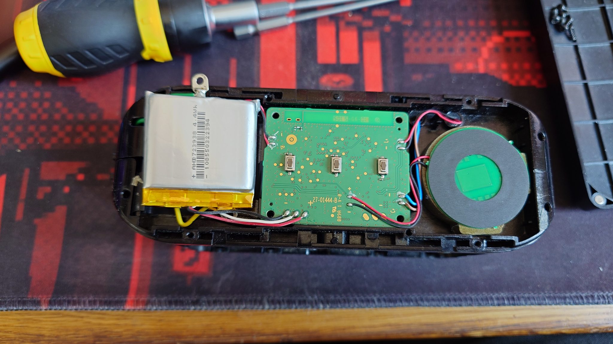
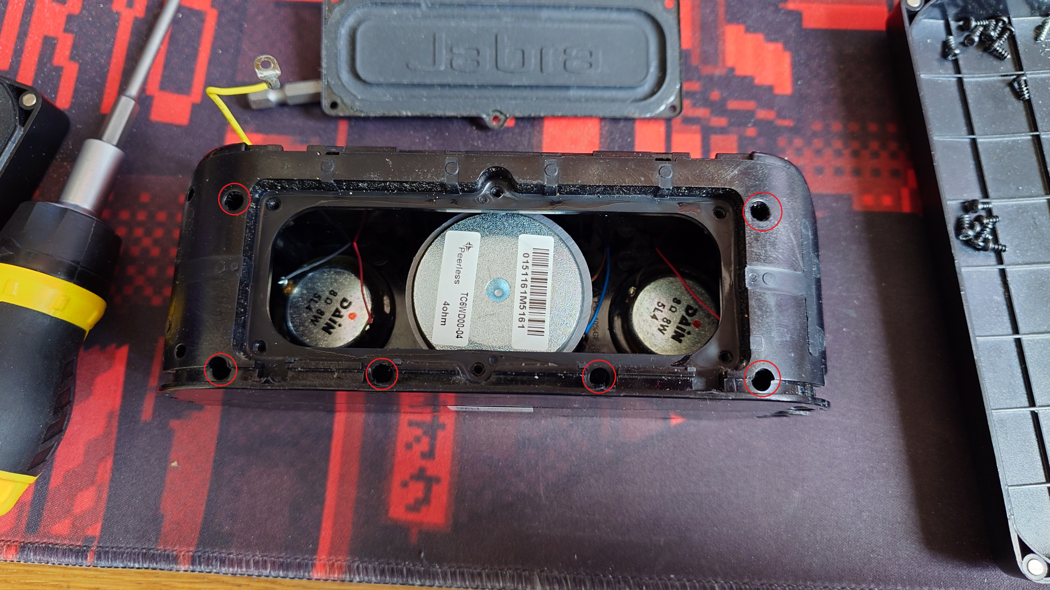
At this point, if your target is just a battery replacement, you can unglue the old battery with a bit of IPA, unsolder pins, resolder it for a new battery, glue it back on some dual sided tape and call it a day. However, in this case it’s safe to have this photo and desolder the battery, NFC transmitter (circle on right) and the speakers from a main board. On this photo I already took down the screws and I believe they are all Torx 7 or 8.
That also lets you take off shielding of the speakers from a case, which can let you clean it up inside (it was really needed after 10 years of use in my case). There is a video from a disassembly on YouTube, where you have to pry metal hinges underneath in order to get this off and I advise against it; I didn’t break them entirely and i was able to bend them back, so they fit nicely, but it’s just a terrible idea.
When you get parts desoldered, disconnect a FFC cable from a connector; you have to take off a green tape and push the black latch up by 90 degrees, so it unlocks the cable.
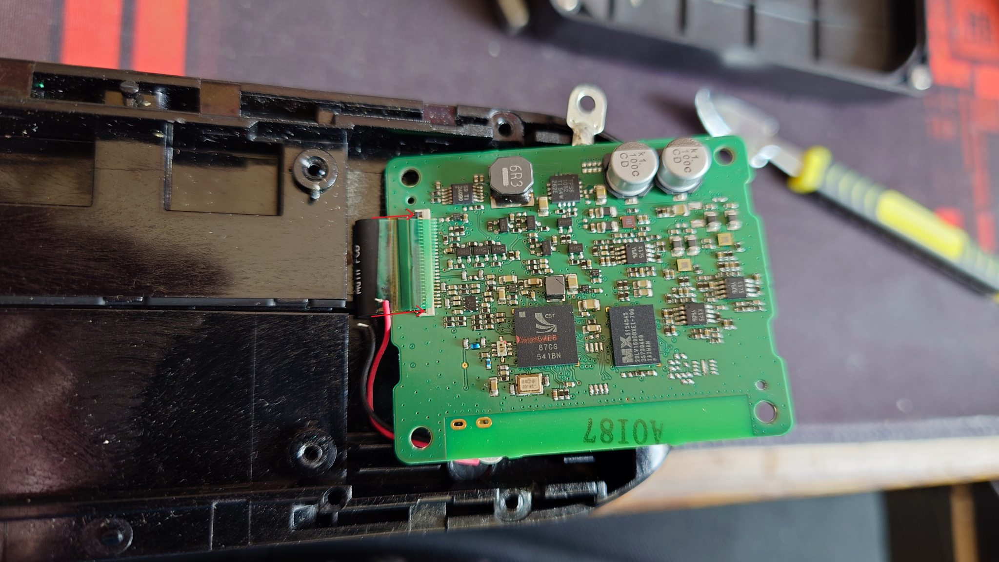
Then, you should patiently take of the cable with a use of IPA, as there is a lot of glue underneath.
In order to get access to the other PCB with USB, Jack and the slide switch, you have to unscrew Torx 7 screws on the lower side of a speaker. You don’t have to take this „Jabra” cover, I was very curious how does it look like inside, however it might be easier to have access here in order to be able to put more pressure on the screws, for me they were very hard to screw off, it was impossible with iFixIt screwdriver, so I bought Torx specific long head screws in order to access the screws deep inside the case.
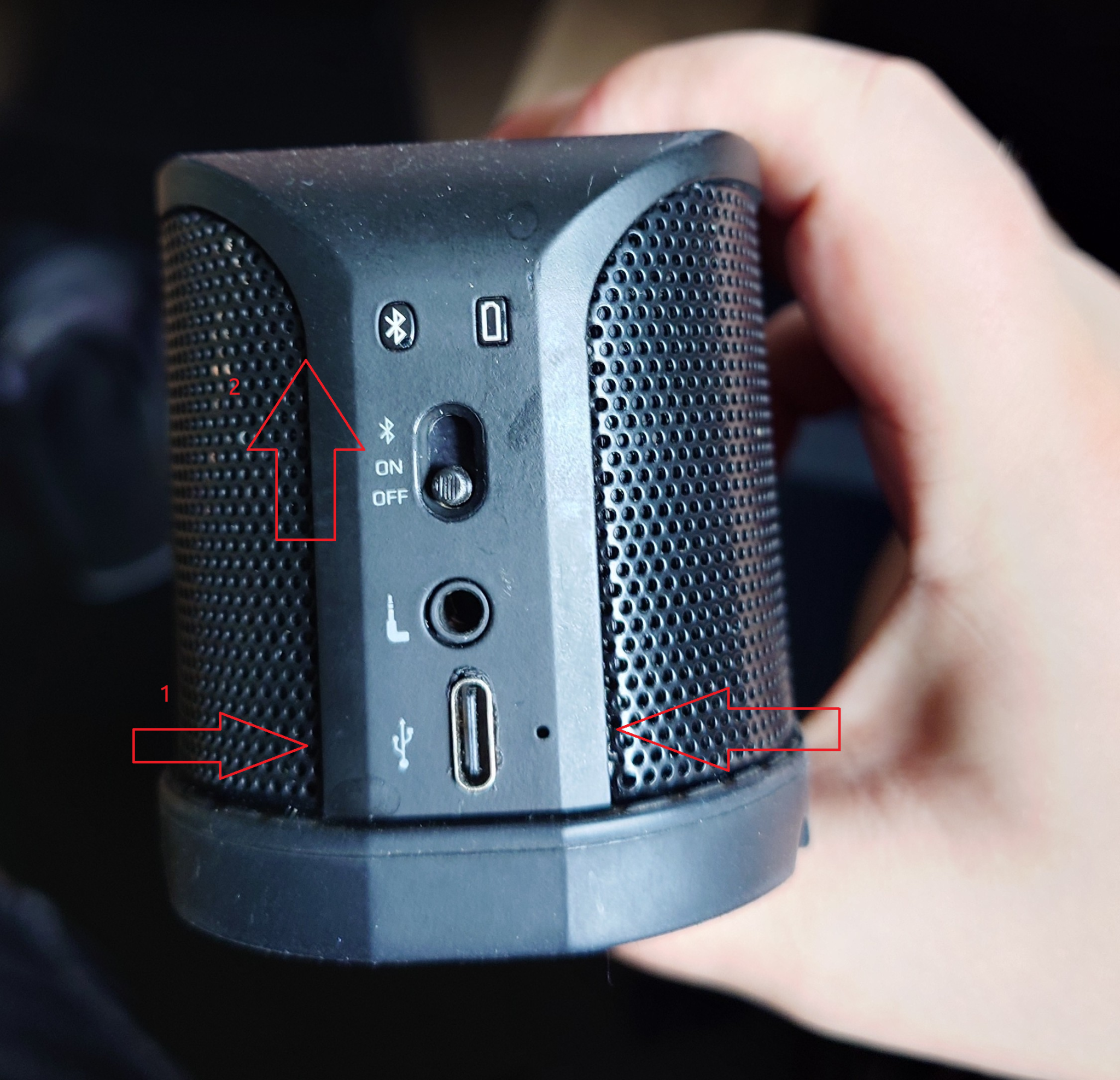
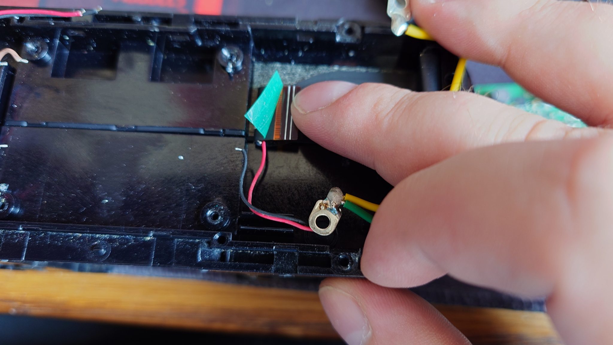
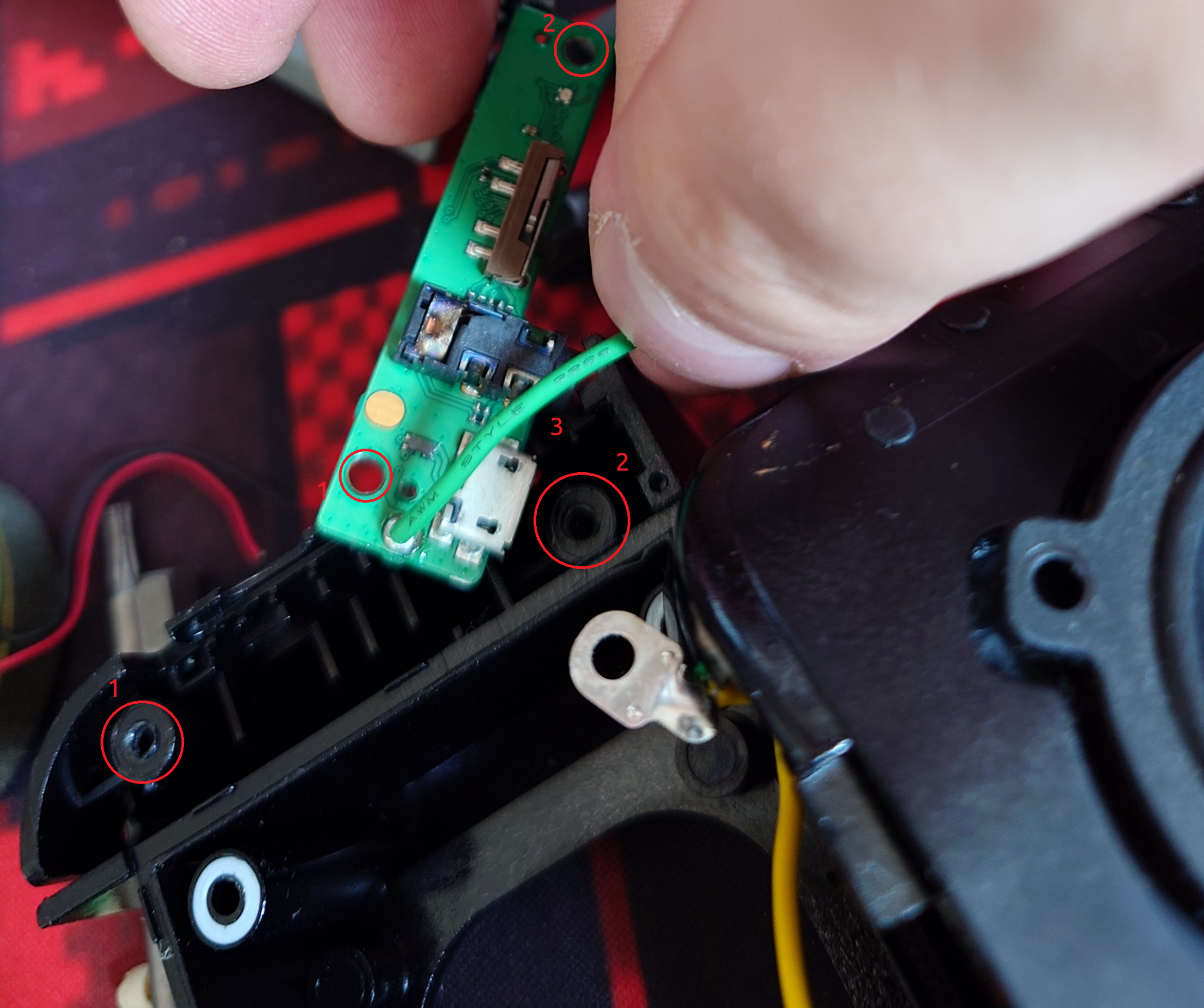
I don’t have a photo of unscrewing the other PCB, but I will describe how to deal with it. I opened the case and plastic elements covering LEDs came off as well as the hinge on a slide switch. I unscrewed 1 and 2 screws, they were Torx 6 I think and I pulled of a microphone (marked as 3) on the photo, so I could take off the PCB for inspection, as well as desoldered a green cable.
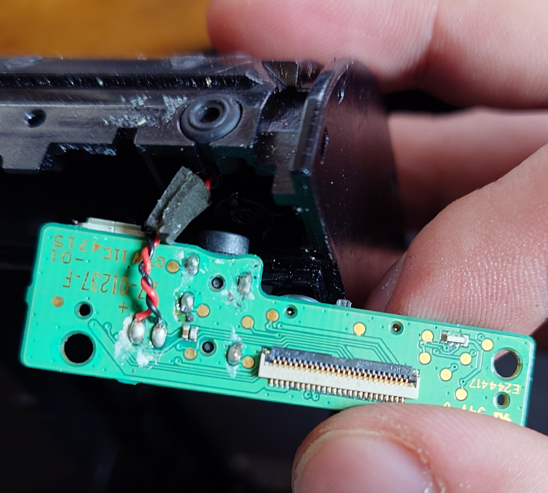
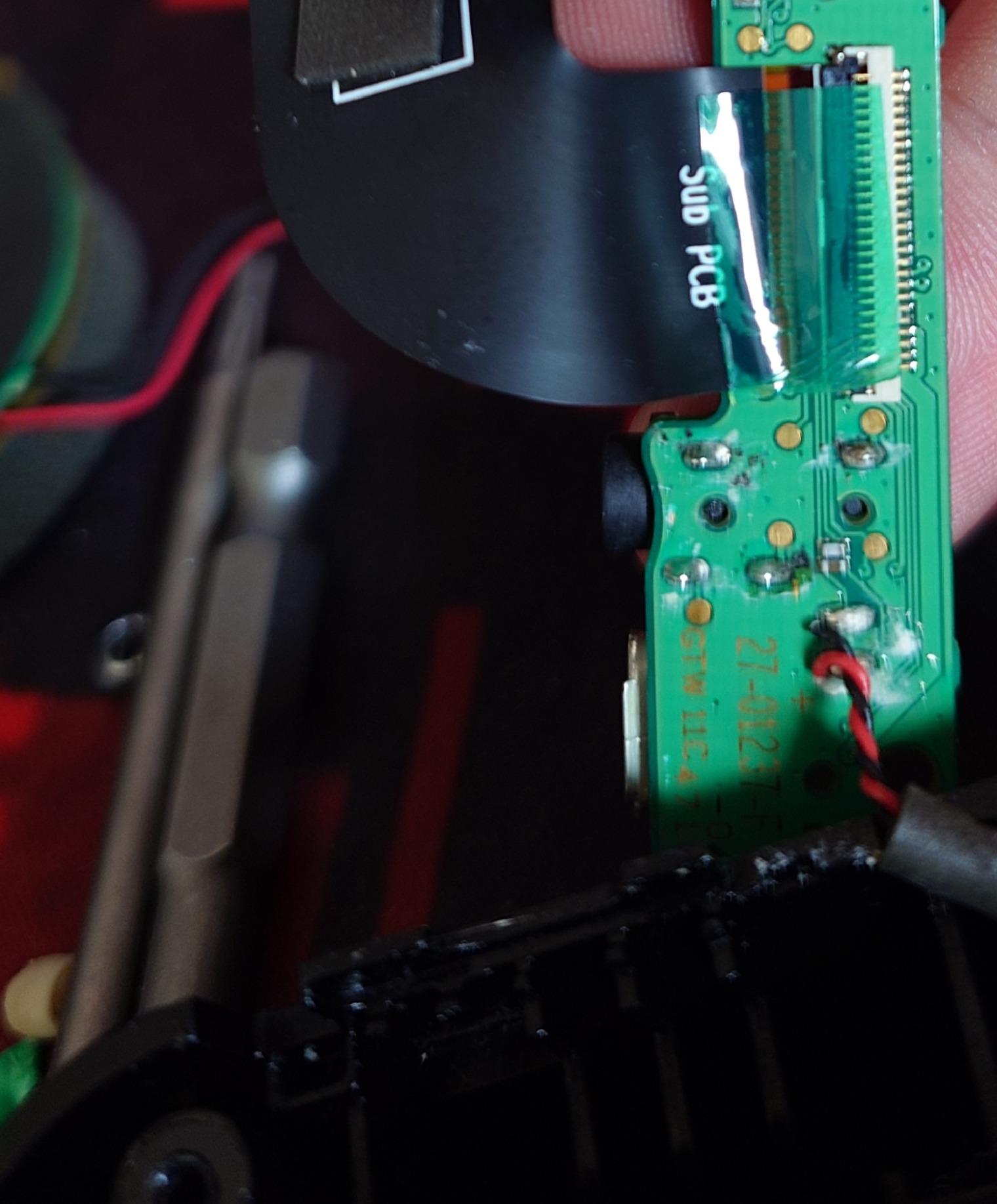
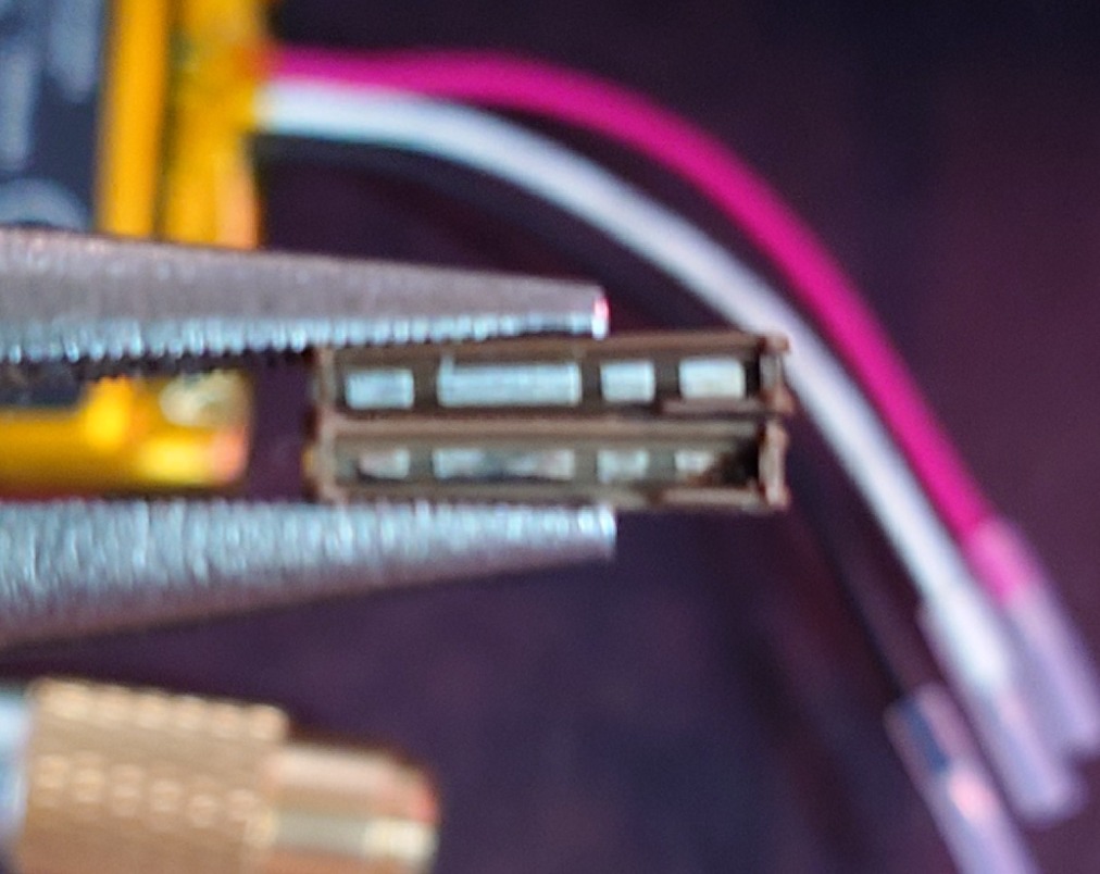
Underneath the PCB there is a second side of a FFC ribbon cable, so make sure you unlatch it as you did with the first side. Here is how it looks with the microphone from below:
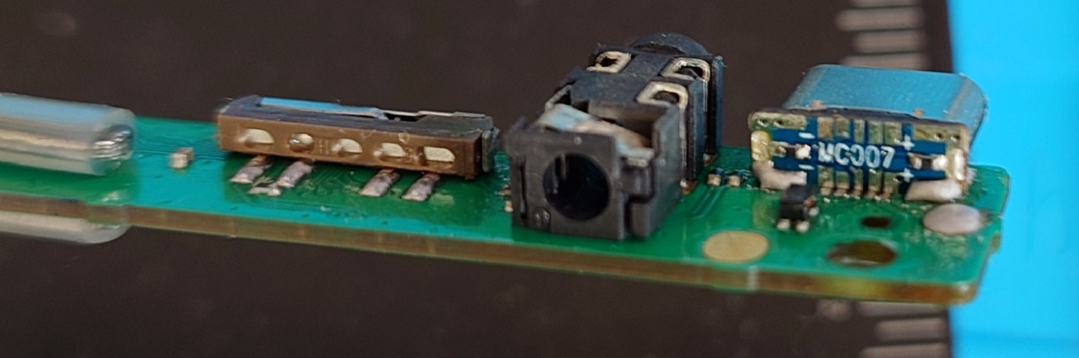
The job
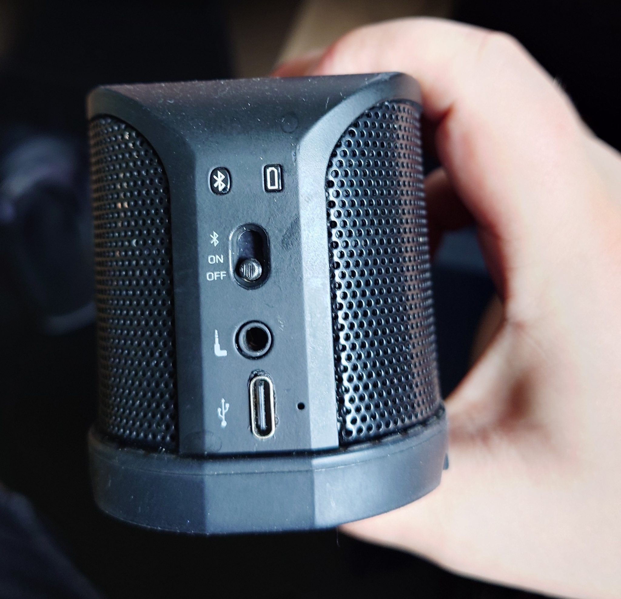
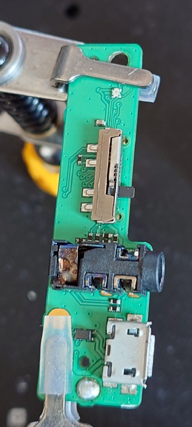
So that’s what we have to work on:
As I said, the switch in question should be kept after desoldering. The switch has 3 positions from bottom to up: OFF, ON, PAIR and this switch has a stem with a slot for a spring, which pushes back the switch from PAIR position to ON. It’s not the end of the world if we just solder in the switch I’ve found, but I have managed to put the stem with spring to a new slider. This is how the slider looks from below (sorry for a blurry photo):
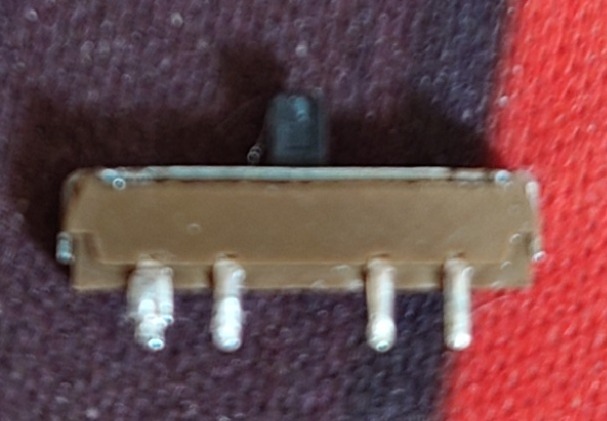
In order to open it, you have to pry a top housing from both sides and then from the top side. The stem and spring will fall off, so make sure you won’t lose it, because they are very small. Let me show you the difference between the damaged base (bottom) and a new one (up):
I put the stem to a new base with a spring, put the top housing from an old switch and pried it back, so it holds the rest nicely inside and soldered it back to the board. I also cleaned up the Jack port with IPA, super fine brush and a lot of patience (10 minutes), so it got a bit shiny. Then, I desoldered the USB port, figured out on which side I can find a GND and 5V pin and soldered the new port in. The photo below wasn’t final, these pins weren’t soldered properly and I got it reflowed with more solder, so it connected 1-5 pins with the board correctly.
The only negative thing about these ports is that they don’t work symmetrically, or at least I didn’t manage to get it work like this. Data connection works only if you put a USB-C cable one way. After that, I used a grinding pen with a lot of patience and grinded the case, so it can fit the PCB with a USB-C port (both the plastic part with glue on the inner part as well as the main case). The final result is at the top of the post. I added a 3D printed hinge, but I don’t share the model, because it wasn’t a perfect fit, but I made it work with a little help of grinding pen again.